EVGA 680i LT SLI: NVIDIA's 680i Cost Reduced
by Gary Key on March 28, 2007 4:00 AM EST- Posted in
- CPUs
Board Layout and Design
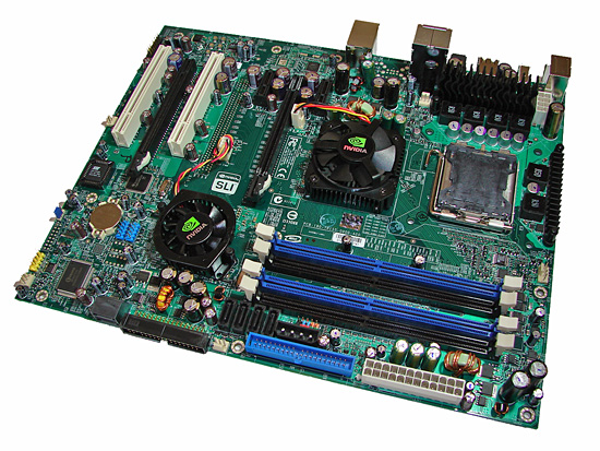
The board layout that NVIDIA devised for the 680i LT chipset is quite good but we would have preferred a black PCB design instead of the pedestrian green. The board easily installed into our Cooler Master CM Stacker 830 case while cable management was good for the optical and hard drives. The board features an excellent six-phase power design and a mixture of conductive polymer aluminum solid capacitors and high-quality aluminum electrolytic capacitors. There are four fan headers (one 4-pin, three 3-pin) located in easy to reach positions on the board but only the CPU fan offers automatic fan control capabilities within the BIOS. Both the SPP and MCP are actively cooled with fans that tended to have a noticeable whine on power-up and remained at 100% speed throughout testing as fan speed cannot be controlled.
Considering other boards in the price range have passive cooling solutions we have to question NVIDIA's decision on using an active cooling solution. We know this is one of the areas targeted for cost reduction but most people will find the noise obtrusive at times, and we are also concerned about the life expectancy of the fans. We do not mind active cooling solutions on chipsets that run hot or on a board designed with overclocking in mind. However, one of the main design objectives with this board was not to encroach upon the 680i boards in overclocking capabilities so this decision is slightly confusing to us.
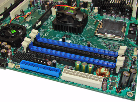
The memory slots are color coded correctly for dual channel operation. The 24-pin ATX power connector is conveniently located with the blue IDE connector on the edge of the board. We would have flipped the IDE connector to a right angle design in order to have opened up a little additional room for the four black SATA ports and 4-pin Molex connector. Unfortunately, one of the worst design decisions on this board was placing the chassis connector panel in between the Molex connector and the fourth DIMM slot.
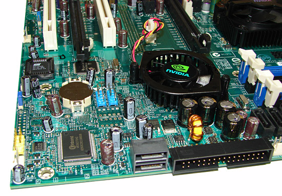
The two primary black SATA ports and the floppy drive connector are located on the edge of the board. We found the positioning of the SATA ports to be very good when utilizing the PCI or second PCI-E x16 physical slot. The MCP is actively cooled and remained fairly warm to the touch throughout testing, although additional cooling was not needed when overclocking. The fan has a low profile and we did not have any issue using our 8800GTX, but again the area around it tended to get hot after stress testing.
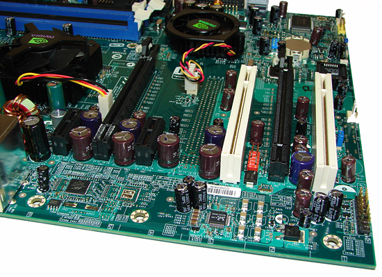
The board comes with two PCI Express x16 connectors, two PCI Express x1, and two PCI connectors. The layout of this design offers a good but not spectacular dual x16 connector design. The second PCI Express x1 slot will be physically unavailable as will the second PCI connector if you utilize a double slot card in either x16 slots. We would also have switched the first PCI and second PCI Express x16 connector in order to give the second video card additional space, as our secondary 8800GTX tended to act like a vacuum cleaner for the bottom of our case. It would have been nice if the second PCI Express x1 connector had been moved to the vacant spot where the missing third x16 slot would have been located. This would have meant that both PCI Express x1 slots would have been open even with dual-slot SLI.
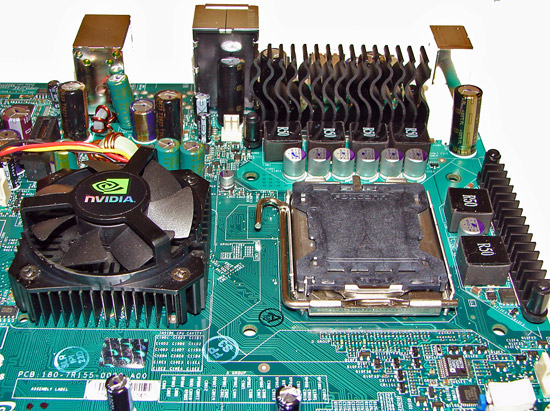
Getting back to the CPU socket area, we find an excellent amount of room for alternative cooling solutions. We utilized the stock heatsink/fan in our normal testing but also verified a few larger Socket-775 air cooling solutions would fit in this area during our overclocking tests. The 680i LT SPP chipset is actively cooled with a mid-rise heatsink/fan unit that did not interfere with any installed peripherals but was loud in our opinion. The VRM components are passively cooled and the 8-pin ATX power connector is located out of the way.
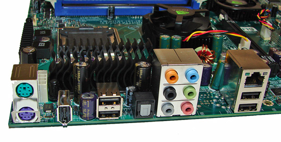
The rear panel contains the standard PS/2 mouse and keyboard ports, LAN port, and four USB 2.0 ports. The LAN port has two LED indicators representing Activity and Speed of the connection through the Marvell Gigabit PCI-E PHY. The audio panel consists of six ports that can be configured for 2, 4, 6, and 8-channel audio along with an S/PDIF optical out port. The I/O panel also features an IEEE 1394a port.
The audio subsystem is based on the Realtek ALC885 and offers 8-channel output. Realtek has had troubles recently with EAX 2.0 support but we did notice a slight improvement in the 1.61 driver set with several games, although Battlefield 2 continues to present problems for Realtek. We continue to feel that the ADI 1988B HD audio codec on the upper end ASUS boards or the Creative X-Fi chipset utilized on the new MSI 680i offer significantly better EAX audio quality in games than the Realtek HD codecs.
Overall, the feature set on this board is good but other boards in this price range offer additional USB and network ports along with passive cooling designs.
 |
| Click to enlarge |
The board layout that NVIDIA devised for the 680i LT chipset is quite good but we would have preferred a black PCB design instead of the pedestrian green. The board easily installed into our Cooler Master CM Stacker 830 case while cable management was good for the optical and hard drives. The board features an excellent six-phase power design and a mixture of conductive polymer aluminum solid capacitors and high-quality aluminum electrolytic capacitors. There are four fan headers (one 4-pin, three 3-pin) located in easy to reach positions on the board but only the CPU fan offers automatic fan control capabilities within the BIOS. Both the SPP and MCP are actively cooled with fans that tended to have a noticeable whine on power-up and remained at 100% speed throughout testing as fan speed cannot be controlled.
Considering other boards in the price range have passive cooling solutions we have to question NVIDIA's decision on using an active cooling solution. We know this is one of the areas targeted for cost reduction but most people will find the noise obtrusive at times, and we are also concerned about the life expectancy of the fans. We do not mind active cooling solutions on chipsets that run hot or on a board designed with overclocking in mind. However, one of the main design objectives with this board was not to encroach upon the 680i boards in overclocking capabilities so this decision is slightly confusing to us.

The memory slots are color coded correctly for dual channel operation. The 24-pin ATX power connector is conveniently located with the blue IDE connector on the edge of the board. We would have flipped the IDE connector to a right angle design in order to have opened up a little additional room for the four black SATA ports and 4-pin Molex connector. Unfortunately, one of the worst design decisions on this board was placing the chassis connector panel in between the Molex connector and the fourth DIMM slot.

The two primary black SATA ports and the floppy drive connector are located on the edge of the board. We found the positioning of the SATA ports to be very good when utilizing the PCI or second PCI-E x16 physical slot. The MCP is actively cooled and remained fairly warm to the touch throughout testing, although additional cooling was not needed when overclocking. The fan has a low profile and we did not have any issue using our 8800GTX, but again the area around it tended to get hot after stress testing.

The board comes with two PCI Express x16 connectors, two PCI Express x1, and two PCI connectors. The layout of this design offers a good but not spectacular dual x16 connector design. The second PCI Express x1 slot will be physically unavailable as will the second PCI connector if you utilize a double slot card in either x16 slots. We would also have switched the first PCI and second PCI Express x16 connector in order to give the second video card additional space, as our secondary 8800GTX tended to act like a vacuum cleaner for the bottom of our case. It would have been nice if the second PCI Express x1 connector had been moved to the vacant spot where the missing third x16 slot would have been located. This would have meant that both PCI Express x1 slots would have been open even with dual-slot SLI.
 |
| Click to enlarge |
Getting back to the CPU socket area, we find an excellent amount of room for alternative cooling solutions. We utilized the stock heatsink/fan in our normal testing but also verified a few larger Socket-775 air cooling solutions would fit in this area during our overclocking tests. The 680i LT SPP chipset is actively cooled with a mid-rise heatsink/fan unit that did not interfere with any installed peripherals but was loud in our opinion. The VRM components are passively cooled and the 8-pin ATX power connector is located out of the way.

The rear panel contains the standard PS/2 mouse and keyboard ports, LAN port, and four USB 2.0 ports. The LAN port has two LED indicators representing Activity and Speed of the connection through the Marvell Gigabit PCI-E PHY. The audio panel consists of six ports that can be configured for 2, 4, 6, and 8-channel audio along with an S/PDIF optical out port. The I/O panel also features an IEEE 1394a port.
The audio subsystem is based on the Realtek ALC885 and offers 8-channel output. Realtek has had troubles recently with EAX 2.0 support but we did notice a slight improvement in the 1.61 driver set with several games, although Battlefield 2 continues to present problems for Realtek. We continue to feel that the ADI 1988B HD audio codec on the upper end ASUS boards or the Creative X-Fi chipset utilized on the new MSI 680i offer significantly better EAX audio quality in games than the Realtek HD codecs.
Overall, the feature set on this board is good but other boards in this price range offer additional USB and network ports along with passive cooling designs.


16 Comments
View All Comments
Stele - Wednesday, March 28, 2007 - link
It boils down to the engineering headroom put into the PWM design. Let's say the maximum supply current anticipated from a generation of CPUs is 50A (usually from datasheets and/or design guidelines from the CPU manufacturer). Motherboard designers can design their PWM to be just sufficient for this - most notably, the MOSFETs chosen may be those that can handle around 75A - or they can build some headroom in and choose MOSFETs capable of, say, 100A.
The former design philosophy saves cost, and after all it gets the job done. However, since the components would be running near their design limit, they would generate quite a bit of heat... especially during spikes of load and/or when new CPUs with even higher current draw (e.g. quad-core CPUs) show up.
The latter design philosophy is more expensive, but because the components would be running well below their rated spec, they fare much better in terms of thermal dissipation (and hence efficiency, as less power is lost as heat). The lower running temperatures also help improve the reliability of the components since less thermal stresses are present. Furthermore, when current loads increase - be it due to sudden load spikes and/or power-hungry CPUs and/or overclocking - they still have a lot of headroom, and so are able to handle the extra load without breaking a sweat. This results in better stability and again, lower heat dissipation compared to lower-spec'ed components at the same load.
In view of this, perhaps one other area that Anandtech could look at when reviewing motherboards is to have an IR thermometer handy (the ones that you can point and measure temperatures of surfaces remotely with) and perhaps measure the temperatures of the chipset and PWM (or at least the temperatures of their heatsinks) at idle and load. It may not be perfect (especially when heatpiped, and a hotter heatsink could also mean that the heat flow from the component to the heatsink is good due to good thermal contact) but imho at least it would give a useful ballpark figure.
Stele - Wednesday, March 28, 2007 - link
Pretty good review, critically assessing the chipset in light of theory (paper specs) as well as reality (actual value for money based on real-world prices and competiting products).IMHO, Nvidia's attempt to create a lower-cost version of the 680i SLI by limiting BIOS options and tossing the odd feature out (like passive chipset cooling and two USB/one network port) seems a little clumsy at best... Instead, I think the hybrid chipset combination used in, for example, the Asus P5N32-E SLI Plus is a more elegant solution. As this review demonstrated, the BIOS options do not necessarily cap the LT's overclocking capability enough to prevent it from being a threat to the 680i SLI's exclusive turf. Indeed, it might well turn out that the latter's sales would not be jeopardised by the LT anyway - not because of the arbitrarily imposed limitations, but because of the almost non-existent price difference between boards based on the two chipsets, considering the lost features.
Meanwhile, other reviews of the P5N32-E SLI Plus have noted that the MCP used is that from the AMD-platform 590 SLI chipset. I wonder if, other than the slight rearrangement of PCI-Express lanes, there are any real differences (e.g. revised/improved networking/disk controller engines etc) between the two MCPs? Or are these blocks nothing more than carried over directly from the 590 SLI? It would be great if Anandtech could look into that.
Lastly, a tiny note - it's a little amusing to note how it must be a bit pedantic to have to spell out the full name of the 'solid' capacitors used... at least Anandtech strives hard to get it right! :) Really, though, for the kind of 'solid' capacitors that we're talking about on most motherboards, "aluminium solid electrolytic capacitors" or even just "solid electrolytic capactitors" (vs. 'regular' (liquid) electrolytic) would do perfectly. Conductive polymer capacitors are generally (though not restricted to) the little rectangular ones such as the ones seen on Asus RoG boards as well as the P5N32-E SLI Plus. Just a thought :)
yyrkoon - Wednesday, March 28, 2007 - link
Well, about the capacitors, I know as per some OEM, anandtech was calling them 'solid state capacitors', which you sound like you know enough about electronics to know this is wrong. Anyhow, several readers, including myself called 'foul', and there you have it . . .JarredWalton - Wednesday, March 28, 2007 - link
There were a few complaints when he used "solid capacitors", so I guess the full name is the safe way to go. LOLStele - Wednesday, March 28, 2007 - link
Oh very true! "Solid capacitors" and "solid state capacitors" (as yyrkoon rightly commented) are both commonly used on many hardware sites, and are both inaccurate. One reason for the repeated complaints, iirc, is that we were simply oscillating between one inaccurate term and another. :P"Solid electrolytic capacitors"... now that is perfectly acceptable, despite a difference of one word. The devil, as they say, is in the details. ;)
yyrkoon - Wednesday, March 28, 2007 - link
You did the right thing Jarred, you know how picky 'us' readers are ;)